
How to Use DC High Voltage Generator
When performing capacitive load tests, be sure to connect a current-limiting resistor.
1. Before use, check the tester for integrity; connecting cables should have no open or short circuits, and the equipment should have no cracks or other damage.
2. Place the chassis and the voltage doubling cylinder in appropriate positions, and connect the power cord, cable, and grounding wire respectively. The protective grounding wire, working grounding wire, and the grounding wire of the discharge rod should all be connected separately to the ground terminal of the test object (i.e., single-point grounding). It is strictly forbidden to connect grounding wires in series. For this purpose, use the dedicated DHV grounding wire.
3. Set the power switch to the OFF position and check that the voltage regulator potentiometer is at zero. The overvoltage protection setting is generally 1.1 times the test voltage.
4. Perform a no-load voltage increase to verify that the overvoltage protection setting is sensitive.
5. Turn on the power switch; the red light will illuminate, indicating that the power is on.
6. Press the green button; the green light will illuminate, indicating that high voltage is connected.
7. Smoothly adjust the voltage regulator potentiometer clockwise; the output voltage will start from zero and increase. After reaching the required voltage, record the ammeter reading for the specified time, and check the control box and high-voltage output line for any abnormalities or sounds.
8. To reduce voltage, return the voltage regulator potentiometer to zero, then press the red button to cut off the high voltage and turn off the power switch.
9. Perform leakage and DC withstand voltage tests on the test object. After confirming that the tester has no abnormalities through inspection, proceed with the leakage and DC withstand voltage tests. Connect the test object and grounding wire, verify correctness, then turn on the power.
10. Increase the voltage to the required voltage or current. The voltage increase rate should be about 3-5 kV/s of test voltage. For large capacitive test objects, monitor the charging current on the ammeter to ensure it does not exceed the maximum charging current of the tester. For small capacitive test objects such as zinc oxide arresters and magnetic blow arresters, first increase to 95% of the required voltage (current), then slowly and carefully increase to the required voltage (current). Then read the voltage (current) value from the digital display. If a 0.75UDC-1mA measurement is required for a zinc oxide arrester, first increase to the UDC1mA voltage value, then press the yellow button; the voltage will drop to 75% of the original and maintain this state. At this point, the current can be read. After measurement, turn the voltage regulator potentiometer counterclockwise to zero and press the green button. To increase voltage again, press the red button.
If necessary, use an external high-voltage divider to compare with the voltage on the control box.
11. After the test, reduce the voltage and turn off the power.
12. Several measurement methods
1) For general measurement, after connecting the wires, first suspend the wire connecting the test object, increase to the test voltage, and read the corona and stray current I during the no-load test. Then connect the test object, increase to the test voltage, and read the total current I1; the leakage current of the test object: Io = I1 - I'
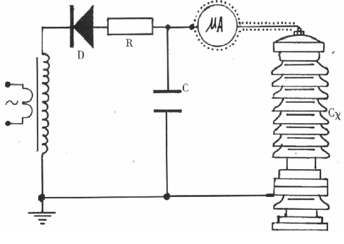
2) When measuring the leakage current of the test object, a high-voltage microammeter should be connected in series on the high-voltage side (see figure below)
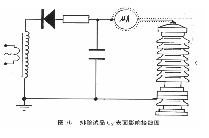
The microammeter must have a metal shield and should be connected to the test object using a shielded wire. The shield lead of the high-voltage lead should be tightly connected to the shield at the instrument end. If the surface of the test object is contaminated, to eliminate the influence of surface leakage current, wrap a bare metal flexible wire tightly around the high-potential end of the test object for several turns and connect it to the shield of the high-voltage lead (see figure below).