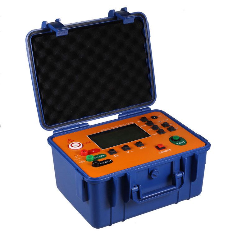
5000V Insulation Resistance Tester Megohmmeter (Electronic) Insulation Resistance Tester Product Features:
1. The insulation test of the meter for 5400 can measure up to 20GΩ at 500V, up to 40GΩ at 1000V, and up to 100GΩ at 2500V; for 5500 type, it can measure up to 100GΩ at 2500V and up to 200GΩ at 5000V; for 5600 type, it can measure up to 200GΩ at 5000V and up to 400GΩ at 10000V.
2. The rated output voltage is maintained for 5400 type with load resistance as low as 4MΩ/8MΩ/20MΩ; for 5500 type, it is 20MΩ/40MΩ; for 5600 type, it is 40MΩ/80MΩ, which enables the meter to accurately measure lower insulation impedance.
3. Automatically switching high and low range dual scale indication, with color scales for easy reading, and LED display in corresponding colors.
4. The whole machine adopts ABS plastic casing with portable design, featuring strong anti-interference capability, compact structure, and beautiful appearance.
5. The meter uses an ultra-thin taut-band meter head, with strong shock resistance.
6. Dual AC/DC power supply, built-in rechargeable battery and intelligent charging module, with high output power (Type C).
7. It is an ideal testing instrument for measuring insulation resistance of transformers, mutual inductors, generators, high-voltage motors, power capacitors, power cables, lightning arresters, etc.
(Electronic) Insulation Resistance Tester Product Technical Parameters:
1. Output voltage: 500V, 1000V, 2500V, 5000V
2. Insulation resistance: 200GΩ
3. Accuracy: 5%
4. High voltage short circuit current: 3mA
5. Insulation performance: When the voltage between the circuit and the casing is 1000V DC, the maximum is 2000MΩ
Product Precautions:
1. The meter can be powered by both AC and DC, but when the on-site power interference is large or unstable, it is recommended to use battery power.
2. When using the rechargeable battery for the first time, it needs to be charged for more than 6 hours. Otherwise, the meter cannot work normally.
3. The charging circuit adopts a dedicated intelligent charging management module, which can automatically stop charging.
Note: The AC input voltage range of the charging adapter is 220V±15%, to avoid unnecessary losses caused by wrong power connection.
4. Insert the DC end of the charging adapter into the meter power jack ⑨, and connect the other end to AC power. The charging indicator (red) lights up, and fast charging begins.
5. When the battery is nearly fully charged, the charging indicator (green) lights up, switching to slow charging state. After a period of time (1-2) hours, the plug can be removed to stop charging and start using the meter.
Note: When the meter is not in use, ensure that the band switch is in the off position to prevent the battery from being used up prematurely.