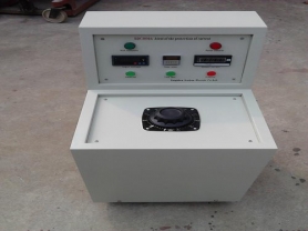
DRDL SeriesHigh Current Generator
is a special equipment designed and manufactured for electrical equipment testing in power departments and industrial/mining enterprises. It is suitable for current load tests and temperature rise tests of various switches, current transformers and other electrical equipment.
This series of products adopts split/integrated structure according to different volume and weight, with features such as stepless adjustment of output current, smooth current rise, wide load variation range, reliable operation, simple and safe operation, etc. It can be used as a current source equipment for current rise or temperature rise tests in industrial and mining enterprises.
II. Main Technical Parameters:
Model
|
Rated Capacity
(KVA)
|
Primary
|
Secondary
|
Structure
Form
|
Current
(A)
|
Voltage
(V)
|
Current
(A)
|
Voltage
(V)
|
DRDL-500
|
3
|
15
|
220
|
500
|
0-5
|
Integrated
|
DRDL-1000
|
5
|
18
|
220
|
1000
|
0-5
|
Integrated
|
DRDL-2000
|
10
|
30
|
380
|
2000
|
0-5
|
Split
|
DRDL-4000
|
24
|
63
|
380
|
4000
|
0-5
|
Split
|
DRDL-5000
|
30
|
79
|
380
|
5000
|
0-5
|
Split
|
DRDL-10000
|
60
|
158
|
380
|
10000
|
0-5
|
Split
|
DRDL-12000
|
72
|
189.5
|
380
|
12000
|
0-5
|
Split
|
DRDL-15000
|
90
|
236.8
|
380
|
15000
|
0-5
|
Split
|
DRDL-20000
|
120
|
315
|
380
|
20000
|
0-5
|
Split
|
Note: When the secondary output is above 6V, it will be designed and manufactured separately according to user requirements.
III. Usage Method:
1. Connect the circuit according to the working principle diagram. The transformer shell and operation console must be well grounded.
2. Connect the power supply, the green indicator light on the operation console will be on, then press the start button, the red indicator light will be on, indicating the current generator is waiting for current rise.
3. Rotate the voltage regulator evenly clockwise to make the output current indication reach the required high current. To ensure testing accuracy, a standard ammeter can be connected in series on the meter terminal.
4. During the test, if any abnormal situation occurs, cut off the power immediately, find out the cause and then conduct the test again.
5. After the test, the voltage regulator must be adjusted back to zero, press the stop button to cut off the power; after cutting off the working power, the test wiring can be removed to ensure safety.
IV. Precautions:
1. This equipment is designed for short-time work, so it is not allowed to work under rated capacity for a long time, especially not allowed to run over rated current to prevent overheating.
2. For transformers that are installed or have been unused for a long time, before operation, use a 1500 megohmmeter to measure the insulation resistance between coils and between coils and ground. Only when the resistance value is not lower than 0.5 megohm can it be used.
3. During use, the current rise transformer and operation console must be reliably grounded to ensure safety.
4. When raising current, it should be done slowly and evenly, and avoid excessive vibration during handling.
5. The contact surface between the voltage regulator and the brush should be kept clean. If necessary, wipe it clean with cotton yarn dipped in 90% alcohol.
6. This equipment should be stored indoors in a clean, ventilated and dry place.