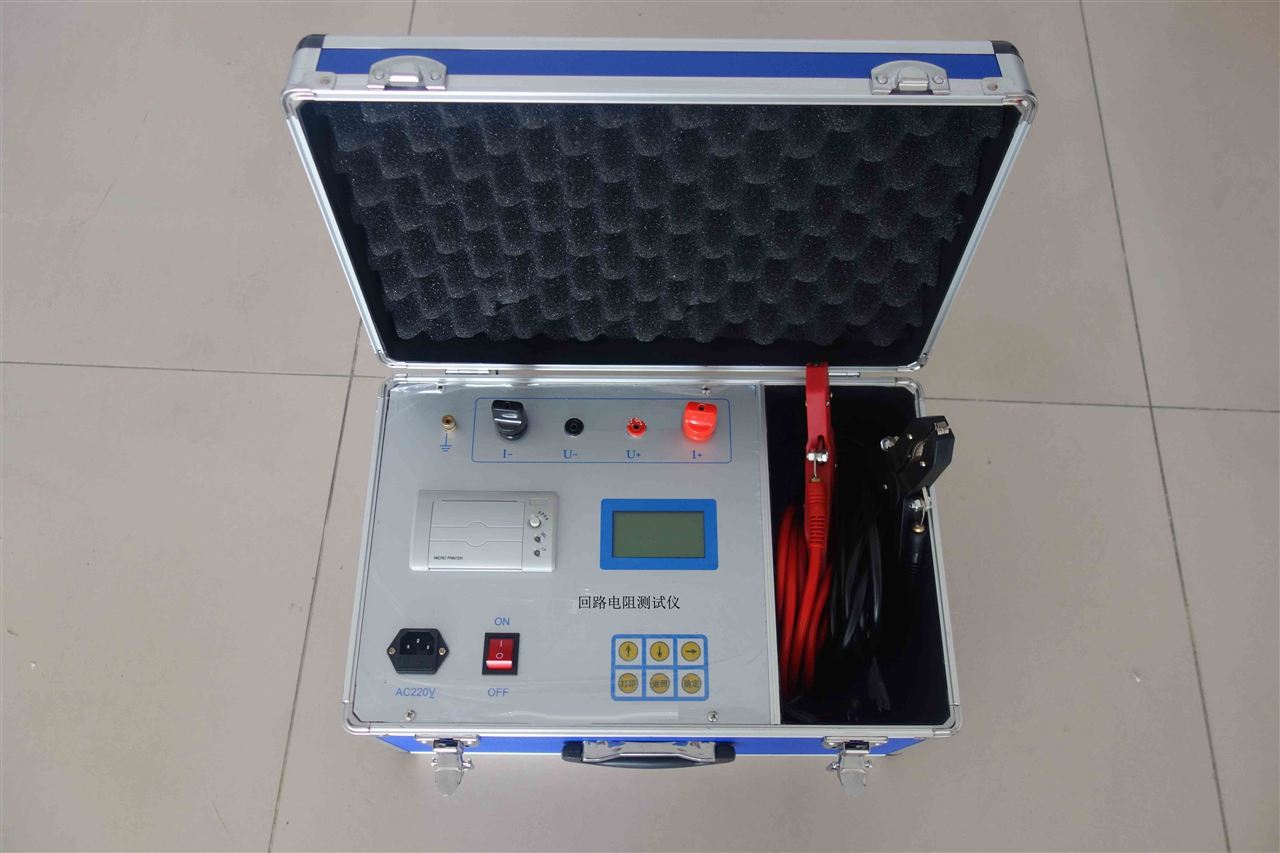
High Voltage Switch Loop Resistance Tester
Performance Features
1. Large test current, fully meeting the national standard requirements for testing contact resistance.
4. Four-terminal connection method effectively eliminates the influence of test lead resistance on test results.
5. Fast test speed, displaying data in about 5 seconds.
6. Capable of continuous long-term operation, equipped with overheat protection circuit, ensuring reliable and stable instrument performance.
7. Easy operation, lightweight, suitable for field work.
Technical Specifications
1. Test current: 100A
2. Range: At 100A 0~20 mΩ
3. Minimum resolution: 0.1μΩ
4. Accuracy: 0.5%±0.2μΩ
5. Output voltage: Maximum DC 10V
6. Working mode: Continuous
7. Power supply: AC220V±10% 50Hz
8. Power consumption: ≤1000W
9. Operating temperature: -20��~40℃
10. Relative humidity: ≤80%, non-condensing
11. Weight: 8.5kg
12. Dimensions: 280mm×235mm×270mm
Operating Procedure
1. Connect according to the four-terminal method.
2. Turn on the power.
3. Press the measurement key (if the current display A value is less than 100A, it can be corrected via the panel current fine-tuning).
4. After the measurement value is displayed, save the data.
5. After measurement, please turn off the power.
6. Please take care of the test clamps.
Instructions for Use
1. According to the four-wire measurement method, use the dedicated test leads to connect the test object to the instrument panel. Note that the voltage measurement leads should be connected inside the current output leads.
2. Connect the AC220V power supply (note: the third wire of the power input, i.e., the protective ground, must be connected to the earth), press the power switch. At this time, the ammeter and resistance meter display "000" (a one-digit fluctuation is allowed before the value stabilizes).
3. Press the measurement switch, adjust the current output knob (clockwise) until the ammeter displays "100.0", then read the number on the resistance meter, which is the resistance value of the test object, and record it. (If "1" is displayed, it indicates the measured circuit is over-range).
4. After testing, turn the current output adjustment knob (counterclockwise) to the minimum, reset the measurement switch, and then turn off the power switch.
5. To repeat the test, simply reset the measurement switch, re-clamp the test clamps, and press the measurement switch again.
Vacuum Switch Loop Resistance Tester