Anti-interference dielectric loss tester:
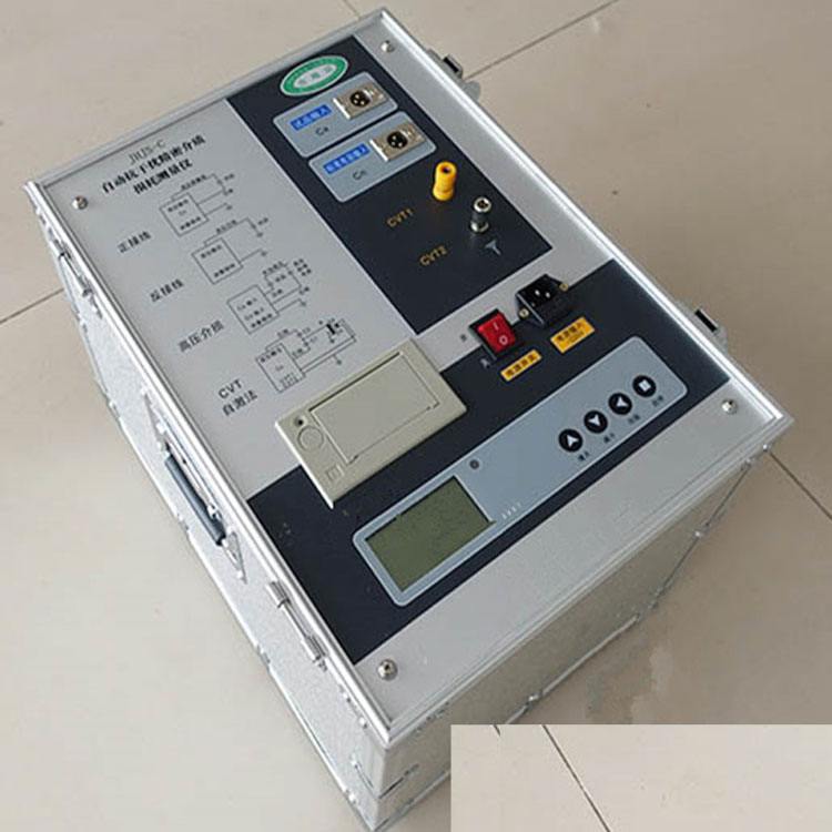
is an instrument for measuring dielectric loss (tgδ) and capacitance (Cx), used to measure the dielectric loss (tgδ) and capacitance (Cx) of various insulating materials, insulating bushings, power cables, capacitors, transformers, and other high-voltage equipment under power frequency high voltage. It has replaced the QS high-voltage bridge, featuring simple operation, Chinese display, printing, convenient use, no conversion needed, built-in high voltage, strong anti-interference capability, and fast testing time (among similar domestic products). It is compact and lightweight, and it is the second-generation
anti-interference dielectric loss tester from our factory.
II. Technical Specifications
1. Ambient temperature: 0 to 40°C (LCD screen should avoid prolonged sunlight)
2. Relative humidity: 30% to 70%
3. Power supply: Voltage: 220V±10%, Frequency: 50±1Hz
4. Dimensions: Length × Width × Height 500mm × 300mm × 400mm
5. Weight: approximately 18Kg
6. Output power: 0.6KVA
7. Display resolution: 3 digits, 4 digits (internally all 6 digits)
8. Measurement range and output voltage selection:
Dielectric loss (tgδ): ±0.00 to ±999%
Test object capacitance (Cx) and applied voltage:
2.5KV range: ≤300nF (300000pF) 3KV range: ≤200nF (200000pF)
5KV range: ≤76nF (76000pF) 7.5KV range: ≤34nF (34000pF)
10KV range: ≤20nF (20000pF)
9. Basic measurement error:
Dielectric loss (tgδ): 1%±7 digits (load current 20uA to 500mA)
Dielectric loss (tgδ): 2%±9 digits (load current 5uA to 20uA)
Capacitance (Cx): 1.5%±1.5pF
III. Structure
The instrument integrates voltage boosting and measurement in one unit, with output voltage adjustable in five ranges from 2.5KV to 10KV to meet various needs. No external equipment is required during measurement, and wiring is similar to the QS bridge but more convenient.
1. Display window — LCD screen. 2. Start lamp — indicates high voltage output.
3. Warning lamp — prompts during operation.
4. Operation keyboard — for selecting quick test, start, stop, print, etc.
5. Printer — prints test results.
6. Voltage selection switch — select the appropriate test voltage during measurement.
7. Power socket — fuse rated 5A. 8. Power switch — power on/off.
9. Ground terminal — must be reliably grounded before use.
★10. Measurement power input terminal Ix — has two leads: the red test clip is the center lead (marked Cx) and should be connected to one end of the test object; the black alligator clip is the shield lead (marked E) and is a reference terminal for the internal high voltage output. In normal (grounded) connection mode, it should be grounded; in reverse connection mode, it should be left floating. For external connection, refer to "External High Voltage Method".
★11. Standard current input terminal IN — used only when measuring with an external standard capacitor; this terminal should be connected to one end of the external standard capacitor. IN must be less than 100mA!
12. High voltage output terminal UH — the yellow test clip is the lead (marked UH) and is connected to one end of the test object.