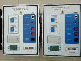
Features and Performance
Used for on-site anti-interference dielectric loss measurement, or precise dielectric loss measurement in the laboratory. The instrument is an integrated structure, built-in dielectric loss bridge, variable frequency power supply, test transformer, and standard capacitor, etc. It adopts variable frequency anti-interference and Fourier transform digital filtering technology, fully automatic intelligent measurement, and the measurement data is very stable under strong interference. The measurement results are displayed on a large screen LCD, and a built-in micro printer can print output.
Main Technical Indicators
Accuracy: Cx: ±(reading×1%+1pF)
tgδ: ±(reading×1%+0.00040)
Anti-interference index: variable frequency anti-interference, can still achieve the above accuracy under 200% interference
Capacitance range: Internal high voltage: 3pF~60000pF/10kV 60pF~1μF/0.5kV
External high voltage: 3pF~1.5μF/10kV 60pF~30μF/0.5kV
Resolution: up to 0.001pF, 4 significant digits
tgδ range: unlimited, resolution 0.001%, automatic identification of capacitance, inductance, and resistance test objects.
Test current range: 10μA~5A
Internal high voltage: set voltage range: 0.5~10kV
Maximum output current: 200mA
Voltage rise/fall method: continuous smooth adjustment
Voltage accuracy: ±(1.5%×reading+10V)
Voltage resolution: 1V
Test frequency: 45, 50, 55, 60, 65Hz single frequency
45/55Hz, 55/65Hz, 47.5/52.5Hz automatic dual frequency conversion
Frequency accuracy: ±0.01Hz
External high voltage: maximum test current 1A for normal connection, power frequency or variable frequency 40-70Hz
Maximum test current 10kV/1A for reverse connection, power frequency or variable frequency 40-70Hz
CVT self-excitation method low voltage output: output voltage 3~50V, output current 3~30A
Measurement time: about 40s, depending on measurement method
Input power: 180V~270VAC, 50Hz/60Hz±1%, mains or generator power supply
Computer interface: standard RS232 interface
Printer: Weihuang A7 thermal micro printer
Ambient temperature: -10℃~50℃
Relative humidity: <90%
1.2 Main Features
1.2.1 Variable frequency anti-interference
Adopting variable frequency anti-interference technology, it can accurately measure under 200% interference, with stable test data, suitable for on-site anti-interference dielectric loss tests.
1.2.2 High-precision measurement
Using digital waveform analysis and bridge self-calibration technologies, combined with high-precision three-terminal standard capacitors, to achieve high-precision dielectric loss measurement.
The input resistance of all ranges of the instrument is less than 2Ω, eliminating the influence of additional capacitance of the measuring cable.
1.2.3 Multi-level safety protection to ensure personal and equipment safety
High voltage protection: short circuit, breakdown, or high voltage current fluctuation of the test object can quickly cut off the output in a short circuit manner.
Low voltage protection: misconnection of 380V, power fluctuation, or sudden power failure triggers protection without causing overvoltage.
Ground protection: when poor grounding of the instrument causes dangerous voltage on the shell, ground protection is activated.
C V T: four protection limits for high voltage and current, low voltage and current, will not damage equipment; wrong menu selection will not output excitation voltage. No 10kV high voltage output during CVT measurement.
Anti-misoperation: two-stage power switch; real-time monitoring of voltage and current; multiple key confirmations; clear distinction between high and low voltage terminals; slow voltage rise, rapid voltage reduction, audible and visual alarm.
Anti-"capacitive rise": when measuring large-capacity test objects, the "capacitive rise" effect of voltage increase may occur. The instrument can automatically track the output voltage to keep the test voltage constant.
Shock resistance: the instrument adopts a unique shock-resistant design, which can withstand strong long-distance transportation vibration and bumping without damage.
High voltage cable: it is a high-voltage resistant insulated wire, which can be used on the ground.
1.2.4 Powerful functions, product serialization
The model of this instrument: F type, specific functions are as follows:
(1) It has normal/reverse connection, internal/external standard capacitor, internal/external high voltage multiple working modes, integrated structure, can do various conventional dielectric loss tests without external auxiliary equipment.
(2) LCD display, menu operation, rich test data, automatic identification of capacitance, inductance, resistance type test objects, built-in micro printer can print output.
(3) It has an external standard capacitor interface, can connect an external oil cup for precise insulating oil dielectric loss test, can connect external solid material measuring electrodes for precise insulating material dielectric loss test, and can also connect an external high-voltage standard capacitor for high-voltage dielectric loss test.
(4) Automatically identifies 50Hz / 60Hz system power supply, and supports generator power supply, even if the frequency fluctuates greatly, it can measure normally.
(5) Built-in series and parallel two dielectric loss measurement models, convenient for instrument calibration.
(6) Can store 255 sets of measurement data.
(7) During CVT self-excitation method measurement, C1/C2 can be measured at one time with one wiring, automatically compensating the influence of bus grounding and standard capacitor voltage division, without changing wires or external accessories.
(8) Chinese graphic menu, large screen backlit LCD display clearer, real-time monitoring of current and voltage.
(9) Optimized circuit design makes the accuracy and stability of normal/reverse connection *.
(10) Automatically identifies external high-voltage test power frequency 40Hz~70Hz, supports power frequency power supply, variable frequency power supply, and series resonance power supply for large-capacity high-voltage dielectric loss tests.
(11) Has reverse connection low-voltage shielding function, under 220kV CVT bus grounding, can perform 10kV reverse connection dielectric loss measurement on C11 without disconnecting wires.
(12) With computer interface. Through this interface, measurement, data processing, and report output can be realized, and the internal measurement software of the instrument can also be upgraded. It can be integrated into a comprehensive high-voltage test vehicle.
(13) Configured with thermal printer, making printing faster, quieter, and clearer.
(14) Added loop poor contact discharge prompt function to facilitate judging whether the wiring is reliable.
(15) Enhanced reverse connection low-voltage shielding function, can measure the capacitance and dielectric loss value of two capacitors at one time with one wiring.
(16) Added CVT ratio function, can measure CVT ratio and phase error.
1.3 Scope of Supply
(1) Instrument main unit (2) User manual and product certificate
(3) Special test cable (4) Power cord
(5) Spare printing paper and fuse tube (6) Others see the "Packing List"
2. Panel Description
2.1 High voltage output socket (0.5~10kV, max 200mA)
Installation position: front side of the box, with protective door outside.
Function: internal high voltage output; detect reverse connection test object current; high voltage terminal of internal standard capacitor.
Wiring method: socket pin 1 connects to high voltage wire core (red clip), pins 2 and 3 connect to high voltage wire shield (black clip). In normal connection, both the high voltage wire core (red clip) and shield (black clip) can be used as voltage application wire; in reverse connection, only the core wire can be used to apply voltage to the high voltage terminal of the test object. If the high voltage terminal of the test object has a shielding electrode (such as a shielding ring at the high voltage end), it can be connected to the high voltage shield; if there is no shield, the high voltage shield is left floating.
Precautions:
(1) The instrument measuring cables are universal, it is recommended to use high voltage wire to connect this socket. The high voltage socket and high voltage wire have dangerous voltage, absolutely prohibit touching the high voltage socket, cable, clips, and live parts of the test object! Confirm power off before wiring, and stay away during measurement!
(2) When using a standard dielectric loss device (or standard capacitor) to verify the reverse connection accuracy, a fully shielded plug should be used to connect the test object, otherwise exposed core wire will cause errors.
(3) Ensure zero resistance connection between the high voltage wire and the high voltage terminal of the test object, otherwise it may cause errors or data fluctuation, and may also cause instrument protection.
(4) When removing wiring under strong interference, disconnect the connection while keeping the cable grounded to prevent induced electric shock.
2.2 Test object input Cx socket (10μA~1A)
Function: input test object current in normal connection.
Wiring method: socket pin 1 connects to measuring wire core (red clip), pins 2 and 3 connect to measuring wire shield (black clip). In normal connection, the core wire (red clip) connects to the low voltage signal terminal of the test object. If the low voltage terminal of the test object has a shielding electrode (such as a shielding ring at the low voltage end), it can be connected to the shield; if there is no shield, the shield is left floating.
Precautions:
(1) It is strictly forbidden to unplug the plug during measurement to prevent the test object current from passing through the human body to the ground!
(2) When using a standard dielectric loss device (or standard capacitor) to verify the normal connection accuracy of the instrument, a fully shielded plug should be used to connect the test object, otherwise exposed core wire will cause errors.
(3) Ensure zero resistance connection between the lead wire and the low voltage terminal of the test object, otherwise it may cause errors or data fluctuation, and may also cause instrument protection.
(4) When removing wiring under strong interference, disconnect the connection while keeping the cable grounded to prevent induced electric shock.
2.3 Standard capacitor input Cn socket (10μA~1A)
Function: input external standard capacitor current.
Wiring method: similar to Cx socket, the difference is:
(1) When using an external standard capacitor, a fully shielded plug should be used for connection. This method is often used for external high voltage level standard capacitors to achieve high voltage dielectric loss measurement.
(2) Select "External Cn" mode in the menu.
(3) Enter the C and tgδ of the external standard capacitor into the instrument to achieve absolute value measurement of Cx capacitance and dielectric loss.
In principle, any capacitor with any capacitance and dielectric loss can be used as a standard capacitor by entering its parameters into the instrument. The difference is that standard capacitors provide better long-term stability and accuracy.
(4) Regardless of whether normal or reverse connection measurement, the standard capacitor wiring method is always normal connection.
2.4 CVT self-excitation method low voltage output socket (3~50V, 3~30A, not available in C type)
Function: output low voltage variable frequency excitation power for CVT measurement from this socket and grounding terminal.
Precautions:
(1) Due to the large low voltage output current, the instrument's special low resistance wire should be used to connect the CVT secondary winding. Poor contact will affect measurement.
(2) Select appropriate voltage and current protection limits from the menu according to CVT capacity.
(3) When starting CVT measurement, output a test voltage of 2~5V. If there is an error in external wiring, it will automatically stop. If suspected instrument failure, measure whether there is this test voltage.
(4) When selecting normal/reverse connection, this output is blocked.
2.5 Measurement grounding terminal
It is connected to the shell and the ground wire of the power socket.
Precautions:
(1) Although the instrument has ground protection, regardless of the measurement, the instrument should be reliably and independently grounded.
(2) Ensure zero resistance grounding. Carefully check that the grounding conductor has no paint or rust, otherwise scrape the grounding conductor clean. Slight poor grounding may cause errors or data fluctuation, and severe poor grounding may cause danger!
2.6 Power input socket (180V~270V 50Hz/60Hz)
Precautions:
(1) The instrument has fast power-off protection function. When the low voltage suddenly loses power, it quickly cuts off the high voltage output in a short circuit manner. This function requires that the low voltage power supply (socket, knife switch, etc.) of the instrument should be reliably connected, otherwise a power failure exceeding a few ms will cause protection.
(2) If the input voltage is greater than 270V (such as misconnection of 380V), the instrument immediately protects and cuts off the internal power supply. After protection, only the main power switch light is on, but the screen has no display. At this time, check the power supply and restart the instrument.
(3) If the voltage is too low and the instrument cannot output the set high voltage, use a voltage regulator to adjust.
(4) The instrument can automatically adapt to 50Hz/60Hz power frequency.
(5) When using generator power supply, the frequency fluctuates greatly, and there is no interference in the occasion of using a generator. You can select "fixed frequency" mode to eliminate the influence of generator power frequency fluctuation.
2.7 Fuse holder
The fuse holder is integrated with the low voltage power socket. The fuse specification is 5A / 250V, size φ5×20mm.
Precautions: Use the same specification fuse. If the fuse blows again after replacing with a spare fuse, the instrument may be faulty. Contact the manufacturer for handling.
2.8 Main power switch
When turning on the main power switch, the instrument name and number are displayed first, and after a few seconds it automatically enters the measurement menu. Turning off this switch also turns off the internal high voltage system power. In emergency situations, this switch should be turned off immediately.
2.9 Keys
(1) "→" moves the cursor, "↑" and "↓" modify the content at the cursor, "OK" is used to confirm or stop. See the "User Manual" of each model for detailed functions. Note: "OK" is one key, do not treat it as two keys.
(2) During measurement, press the "OK" key to terminate the measurement.
2.10 LCD display
Displays menus, measurement results, or error messages. Avoid prolonged sunlight exposure and heavy pressure.
2.11 Printer
Manual printing: when printable data is displayed, press the "Print" key to print.
Automatic printing: after selecting automatic printing in the menu, the result is automatically printed after measurement, and then the instrument power can be cut off from a distance, making operation safer.
Paper and ribbon replacement: the printer is M150 micro printer. The paper width is 44mm. When replacing paper, pull out the printer as a whole, insert the paper into the paper inlet and press the paper feed key. When replacing the ribbon, remove the top cover and install the ribbon flat.
E and F types are equipped with thermal printers, using 44mm wide thermal paper. When replacing paper, open the paper compartment cover of the printer, put in the paper roll and leave a small part outside, then close the cover.
2.12 Communication interface
Function: RS232 interface, connected to the serial communication port of a PC or laptop. To ensure normal communication, both parties should set the same baud rate and communication address.
Communication protocol: the instrument communicates with the PC according to the specified protocol, operates the instrument in real time, and realizes functions such as data storage and transmission.
3. User Instructions
3.1 Contrast adjustment
The contrast of the LCD display has been calibrated at the factory. If you feel it is not clear enough, you can adjust it as follows:
Hold ↑ or ↓ without releasing, then turn on the main power switch, then press ↑ or ↓ to adjust the display contrast. After adjustment, press the "OK" key to exit.
3.2 Entering the menu
After turning on the main power switch, the startup screen is displayed first:

Then automatically enter the measurement menu.

3.3 Selecting wiring mode
The cursor is on "Normal connection", press ↑↓ to select "Normal connection", "Reverse connection", and "CVT" measurement modes.
3.4 Selecting internal or external standard capacitor
The cursor is at ②, press ↑↓ to select "Internal standard" "External standard", indicating the use of internal or external standard capacitor. Usually, the internal standard can be used for normal/reverse connection measurement and CVT self-excitation method measurement. For high voltage dielectric loss, select the external standard mode, and the external capacitor parameters need to be entered into the instrument. The cursor is on "External cn", hold the "Start/Stop" key for more than 1s to display the external standard capacitance value, press ↑↓ keys to modify this value. After modification, hold the "Start/Stop" key for about 1s, hear a beep, release the keyboard to save.
3.5 Selecting test frequency
3.5.1 Default frequency at startup
The cursor is on "Variable frequency", indicating 45/55Hz automatic frequency conversion. The instrument automatically measures at 45Hz and 55Hz once each, and then calculates the data at 50Hz without interference. The default mode at startup is this mode, it is recommended to use.
3.5.2 Selecting more frequencies
The cursor is on "Variable frequency", hold the "Start/Stop" key for more than 1s to switch to full frequency selection, press ↑↓ keys to cycle through "45Hz / 50Hz / 55Hz / 60Hz / 65Hz / 50±5Hz / 60±5Hz / 50±2.5Hz":
"50Hz": power frequency measurement, this setting cannot resist interference, choose it for laboratory measurement or calibration.
"45/55/60/65Hz": single frequency measurement, choose it when studying the change of dielectric loss at different frequencies.
"50±5Hz": 45/55Hz automatic frequency conversion, suitable for measurement under 50Hz power grid power frequency interference.
"60±5Hz": 55/65Hz automatic frequency conversion, suitable for measurement under 60Hz power grid power frequency interference.
"50±2.5": 47.5/52.5Hz automatic frequency conversion, suitable for measurement under 50Hz power grid power frequency interference.
Hold the "Start/Stop" key for more than 1s to cancel full frequency selection.
3.6 Selecting test high voltage
3.6.1 Selecting high voltage in normal/reverse connection mode
The cursor is on 10kV, press ↑↓ keys to cycle through test high voltage "0.5 /0.6 /0.8 /1 /1.5 /2 /2.5 /3 /3.5 /4 /4.5 /5 /5.5 /6 /6.5 /7 /7.5 /8 /8.5 /9 /9.5 /10kV". The test high voltage should be selected according to the high voltage test regulations.
After starting measurement, this place displays the measurement high voltage. Below it displays In=158uA Ix=10mA
In=158uA indicates the current flowing through the standard capacitor, unit is uA.
Ix=10mA indicates the current flowing through the test object, unit is mA.
If In=000 uA, it means the internal high voltage has no output, or the instrument has