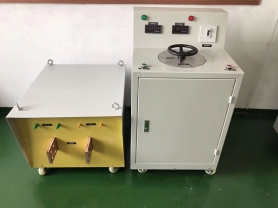
Product Characteristics of Induced Overvoltage Withstand Test Device for Undertaking Electric Power Facilities
Three single-phase transformers have their primary windings connected in a star configuration, and the secondary windings connected in an open delta. When a symmetrical three-phase sinusoidal power supply is applied to the primary side, and the voltage is raised to saturate the iron core's magnetic circuit, the content of the third harmonic component in the magnetic flux increases, correspondingly increasing the third harmonic voltage induced in the iron core coils.
The 150 Hz (three times the power frequency) induced voltage output from the secondary side of the open delta generator serves as the test power supply voltage for the triple frequency.
When the triple frequency generator is loaded (for example, with a JCC——220 type high-voltage cascade voltage transformer), its current changes from inductive to capacitive. Due to the low power factor, the generator's efficiency is relatively low, generally only about 20%. Therefore, a reactor can be connected to an idle winding of the test object for current compensation to improve the power factor of the entire test circuit. Product Application
It is a lightweight test device based on the principle of utilizing the saturation characteristics of the magnetization curve of silicon steel sheet cores in the power frequency grid, inducing a zero-sequence third harmonic electromotive force in the secondary coil of the transformer connected in an open delta configuration.
Technical Parameters
Device Capacity: 10kW.
Input Voltage: AC, three-phase, 380V±10%.
Power Frequency: 50Hz.
Output Voltage: 0 ~ 400V
Output Frequency: 50Hz, 100Hz, 150Hz, 200Hz (optional).
Waveform Distortion Rate: <3%.
Product Applications:
1. AC withstand voltage test for 6kV-500kV high-voltage cross-linked cables
2. Power frequency withstand voltage test for 6kV-500kV transformers
3. AC withstand voltage test for GIS and SF6 switches
4. AC withstand voltage test for generators
5. AC withstand voltage test for other high-voltage power equipment such as busbars, bushings, and instrument transformers.
Usage Methods:
1. With voltage regulator (3kVA~10kVA)
1) Connect according to the wiring diagram, then adjust the overcurrent protection current value based on the test object.
2) Set the voltage regulator to the lowest position, turn on the power switch, the zero position indicator light will illuminate, check for phase loss, and start the test bench.
3) Adjust the voltage regulator so that the triple frequency output voltage reaches the test voltage. Use an oscilloscope to measure the output voltage waveform, frequency, and voltage value to meet the test requirements of the test object.
4) After the test, adjust the voltage regulator to reduce the triple frequency output voltage to zero, the zero position indicator light will illuminate, then open the switch.
5) Turn off the power supply, and the test is completed.
2. Without voltage regulator (10kVA~1000kVA)
1) Connect according to the wiring diagram, then adjust the overcurrent protection current value based on the test object.
2) Set the inductor to a high position, turn on the power switch, check for phase loss, and start the test bench.
3) Adjust the inductor handle to increase the voltage on the voltmeter. When the current is at its minimum, resonance occurs, reaching the test voltage value. Measure the output voltage waveform, frequency, and voltage value until the test power supply requirements of the test object are met.
4) After the test, adjust the inductor handle to reach the high position.
5) Turn off the power switch, and the test is completed.