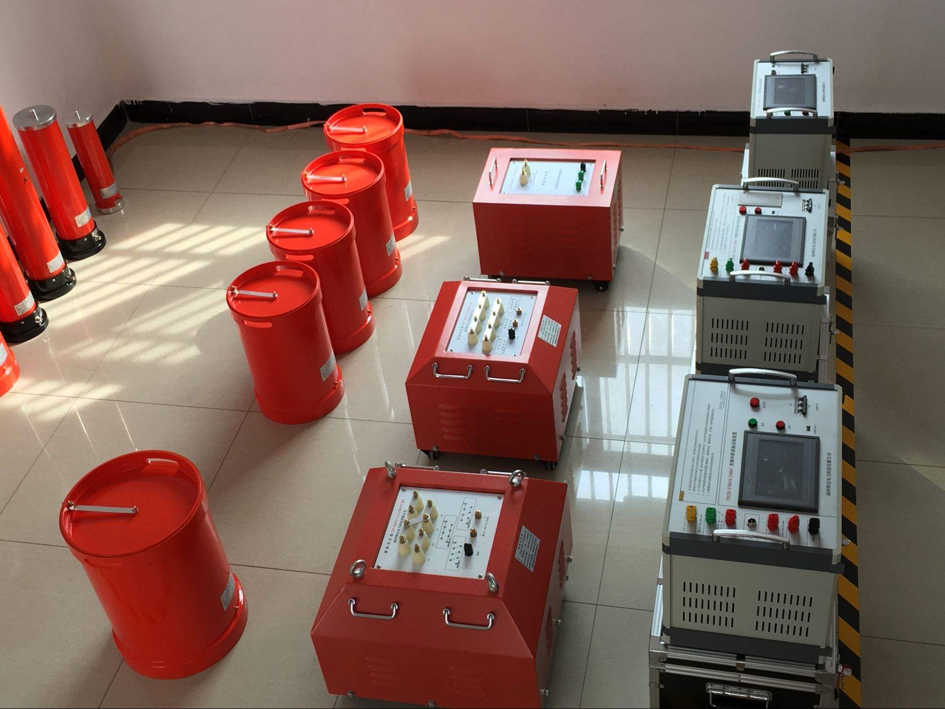

Instructions for Five-Level Test Equipment DC High Voltage Generator 60KV/2mA
1. Instructions for Panel Components
(1) High-frequency output and voltage/current measurement cable quick-connect multi-pin
Socket: Used to connect the main unit to the voltage doubling section. When connecting, align the white dot on the cable plug with the white dot on the socket and turn clockwise until it locks. To disconnect, turn the cable plug counterclockwise.
Note: When installing or removing the plug, hold the metal ring of the plug and rotate. Do not rotate or pull the cable itself to avoid breaking the connection between the plug and the cable.
(2) Digital Voltmeter: LCD digital display of DC high voltage output, unit in kV, minimum resolution of ±0.1kV.
(3) Digital Ammeter: LCD digital display of DC high voltage output current, unit in uA, minimum resolution of ±0.1uA.
(4) Power Fuse Holder: Fuse rating is 5A.
(5) Power Input Socket: Single-phase AC 220V±10%, 50Hz. Connect the provided power cord to this socket (the socket has a built-in 5A fuse or a separate fuse holder).
(6) Grounding Terminal: Connect this grounding terminal, the grounding terminal of the voltage doubling cylinder, and the test object grounding together, then connect to the grounding grid.
(7) Overvoltage Setting Dial Switch: Used to set the overvoltage protection value. The overvoltage setting range is 0.05-1.2 times the rated voltage. The value displayed on the dial switch is in kV.
(7) 75% VDC-1mA Yellow Illuminated Button: Active when the red light is on. When the yellow button is pressed, the yellow light turns on, and the output high voltage drops to 0.75 times the original value and maintains this state. This function is specifically for quick measurement of zinc oxide surge arresters at 0.75VDC-1mA. Press the green button to turn off both red and yellow lights, cutting off the high voltage and exiting the 0.75 times state.
(10) Green Illuminated Button: Green light indicates power is on and high voltage is off. When the red light is on, pressing the green button turns off the red light and turns on the green light, cutting off the high voltage circuit.
(11) Red Illuminated Button, High Voltage On Button, High Voltage Indicator: When the green light is on, pressing the red button turns on the red light and turns off the green light, indicating the high voltage circuit is connected. At this point, voltage can be increased. This button is only effective when the voltage adjustment potentiometer is at zero. If the red light turns on but the green light remains on when pressing the red button, and the red light turns off and green light turns on when releasing, it indicates the internal protection circuit has activated.
In this case, turn off the power and check whether the overvoltage setting dial switch is set to less than 5% of full scale and whether there are any other faults. After confirming no issues, restart the device.