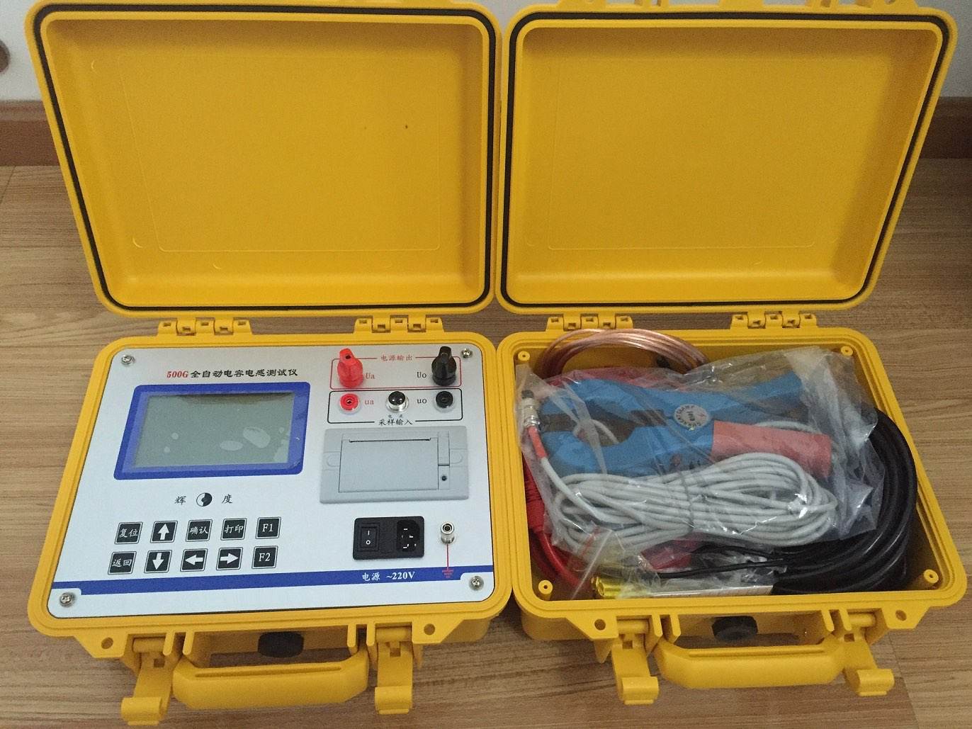
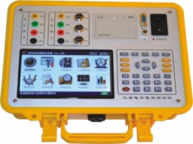
Automatic Capacitance Current Tester
Features
This instrument can measure individual single-phase capacitance of grouped parallel capacitors and three-phase capacitance of various connection types without disconnecting wires. It can also measure the inductance of various reactors, meeting multiple on-site needs.
The instrument features a 7-inch backlit true-color LCD display, ensuring clear visibility in all weather conditions, with a full Chinese menu for easy operation.
It has a built-in large-capacity non-volatile memory: can store 200 sets of measurement data.
It includes a high-precision real-time clock: allows date and time calibration.
It comes with a high-speed micro thermal printer: can print measurement and historical data.
It has overcurrent protection for the test power supply: short circuit of the power output will not damage the instrument.
Technical Specifications
Output Voltage ~2V, ~30V
Measurement Range Capacitance: 2uF~2000uF
Inductance: 1mH~10H
Measurement Accuracy Capacitance: ±(1%+2 digits)
Inductance: ±(1%+5 digits)
Current: ±(1%+2 digits)
Voltage: ±(1%+2 digits)
Dimensions 379mm×278mm×190mm
Weight 8kg
4. Operating Conditions
Ambient Temperature -10℃~50℃
Ambient Humidity ≤85%RH
Power Supply AC220V±10%
Power Frequency 50±1Hz
Power Consumption 500W
5. Panel Introduction
UA, UB, UC, UN: Test line power voltage output terminals. The instrument wiring is distinguished by standard colors.
IA, IB, IC: Current clamp connection input terminals. Please note the markings on the current clamps correspond to these terminals.
Power Socket: Connect to external 220V single-phase AC power, with built-in 5A fuse.
Power Switch: Turn on and off the AC power.
: Instrument grounding terminal
LCD Screen: Displays operation prompts and measurement data
Keyboard: For various instrument functions
Printer: Prints various measurement data
Precautions
8.1 Before using this instrument, please read the user manual carefully, check that the wiring is correct and the grounding is good.
8.2 The high-precision current clamps are key components for measurement. Damage to them can greatly affect test data. Handle with care, do not drop or bump them.
8.3 After completing the measurement and exiting the measurement state, turn off the instrument power before disconnecting the wiring.
8.4 If any unsolvable problem occurs, please contact our company promptly.