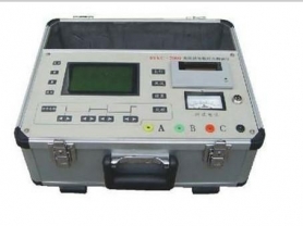

A circuit resistance tester is a specialized device used to measure the contact resistance or conductive circuit resistance between two points in an electrical system. Such testers are widely used in power systems, industrial manufacturing, maintenance and inspection, and are particularly important for measuring the contact resistance of key components such as high-voltage circuit breakers, disconnectors, and busbar connection points. By using a circuit resistance tester, the quality of electrical connections can be effectively evaluated, potential safety hazards can be identified, and the safe and stable operation of the system can be ensured.
Main Uses
Circuit Breaker and Switchgear Testing: Used to measure the contact resistance between the contacts of high-voltage circuit breakers and disconnectors to ensure they can operate normally under high current loads.
Busbar and Cable Joint Testing: Checks the resistance values at busbar connection points and cable joints to identify high-resistance connection points caused by corrosion, loosening, and other reasons, preventing overheating faults.
Other Electrical Connection Testing: Suitable for various occasions requiring precise resistance measurement, such as transformer winding connections and grounding systems.
Working Principle
The circuit resistance tester is typically based on the four-terminal method (Kelvin connection) for measurement, which effectively eliminates the influence of lead resistance on the measurement results. During the test, the instrument applies a constant DC current (usually ranging from 10A to several hundred amperes) to the circuit under test and measures the voltage drop across the resistance under test through a separate pair of voltage detection leads. According to Ohm's law
Features and Functions
High Current Output: To simulate the current load under actual working conditions, many circuit resistance testers can provide high current output up to several hundred amperes.
High Precision Measurement: Provides micro-ohm level or even lower resolution to ensure the accuracy of measurement results.
Automatic Temperature Compensation: Considering the influence of temperature on resistance values, some advanced models are equipped with temperature compensation functions to provide corrected resistance values under different ambient temperatures.
Data Storage and Transmission: Supports storage of measurement data and can transmit data to a computer for further analysis via interfaces such as USB and Bluetooth.
Development Trends
With the development of technology, circuit resistance testers are becoming more intelligent and portable:
User Interface Optimization: Modern devices are often equipped with touchscreen interfaces, making operation more intuitive and convenient.
Application of Wireless Communication Technology: Makes data processing and sharing easier, improving work efficiency.
Improving Test Speed and Accuracy: Manufacturers continuously explore how to shorten test time while ensuring measurement accuracy to better adapt to on-site testing needs.
In summary, the circuit resistance tester is an important tool for ensuring the safe and stable operation of electrical systems. Whether it is quality control of new equipment or maintenance inspection of old equipment, it plays an irreplaceable role. With the advancement of technology, such testers will continue to evolve, providing more efficient and accurate solutions.